Is your air conditioner blowing warm air when it should be ice cold? One of the most frequent culprits behind AC malfunctions is a faulty capacitor. This article provides a comprehensive guide on how to test air conditioner capacitors, which are critical components for keeping your AC system running smoothly. In fact, AC capacitor failure is a very common cause of air conditioner malfunctions. Capacitor-related issues are responsible for a significant percentage of “no-cool” service calls, especially when the summer heat is at its peak. Studies by HVAC service providers indicate that these issues account for up to 70% of such calls during heat waves. That’s a lot of no-cool calls!
In this guide, we’ll cover everything you need to know about testing AC capacitors. We’re talking visual inspection techniques to spot obvious problems, essential safety precautions to keep you safe, detailed multimeter testing procedures to get accurate readings, and a thorough understanding of the common causes of capacitor failure so you can prevent future issues. By the end, you’ll be well-equipped to diagnose and address capacitor problems in your AC system.
Whether you’re a homeowner looking to understand your AC system better or an HVAC professional seeking a refresher, this article is for you. Our goal is to provide clear, practical steps for those new to AC repair, while also offering in-depth theoretical knowledge for those with more experience. We’ll strike a balance between hands-on application and the underlying science, ensuring clarity without skimping on the technical details. So, let’s dive in!
What is a Capacitor?
So, what exactly is a capacitor? In simple terms, it’s a passive electronic component that stores electrical energy in an electric field. Think of it like a tiny, super-speedy rechargeable battery. However, there’s a key difference: unlike a battery that stores energy through chemical reactions, a capacitor stores energy electrostatically, directly within an electric field. This means a capacitor can charge and discharge much faster than a battery – imagine a camera flash versus a car battery. But, it also means a capacitor typically stores far less energy for its size. So, while a battery might power your phone for a day, a capacitor is better suited for providing quick bursts of energy.
A capacitor is built from two conductive plates – usually metal, like aluminum – separated by a non-conductive material called a dielectric. Think of the plates as the areas where electrical charge builds up. The dielectric sits between these plates, and its main job is to prevent electricity from flowing directly between them. This allows an electric field to form and store energy. The dielectric also significantly boosts the capacitor’s ability to store charge. A material’s “dielectric constant” indicates how well it can store energy; the higher the constant, the more energy the capacitor can hold at a given voltage. Common dielectric materials include ceramic (like you find in some insulators), film (often metallized polypropylene), and electrolytic materials. Metallized polypropylene film capacitors are frequently used in AC motor applications because they offer high insulation, low energy loss, and a neat “self-healing” property we’ll discuss later. Electrolytic capacitors are typically used where you need a lot of capacitance in a small package, like in motor-start applications, but they don’t last as long and are more sensitive to temperature and voltage. Ceramic capacitors are less common in AC motor applications themselves, but you might find them in some of the electronic circuits within the AC unit.
Capacitance is simply a measure of how much electrical charge a capacitor can store. It’s measured in Farads (F), but in AC applications, you’ll usually see microfarads (µF), which are millionths of a Farad. Think of capacitance like the size of a bucket: a bigger bucket (higher capacitance) can hold more water (electrical charge) at a given level (voltage). The relationship between charge (Q), voltage (V), and capacitance (C) is expressed by the formula C = Q/V. So, a capacitor with a higher capacitance can store more charge at the same voltage. What determines capacitance? It’s all about the capacitor’s physical characteristics: the area of the plates, the distance between them, and the dielectric constant of the material nestled in between.
How does a capacitor actually work? When you apply a voltage (electrical pressure) across a capacitor, electrons (tiny negatively charged particles) start piling up on one plate, giving it a negative charge. At the same time, the other plate loses electrons and develops a positive charge. This charge imbalance creates a potential difference, or voltage, between the plates – like building up pressure in a water tank. Now, if you provide a path for the electrons to flow (like closing a switch in a circuit), they’ll rush from the negatively charged plate to the positively charged plate, releasing the stored energy – like opening the valve on that water tank.
Capacitors act differently depending on whether they’re in a DC (direct current) or AC (alternating current) circuit. Think of DC like a steady stream of water, and AC like waves in the ocean. In a DC circuit, once the capacitor is fully charged, it’s like a dam blocking the water flow – no more current can pass. However, in an AC circuit, the voltage is constantly changing direction, so the capacitor is continuously charging and discharging, allowing current to flow through the circuit, like a buoy bobbing up and down in the waves. This AC behavior is crucial for many applications, especially AC motors. AC motors need a “phase shift,” which capacitors help create. This phase shift is a slight difference in timing between the current and voltage, and it’s what allows the motor to generate a rotating magnetic field and produce torque (rotational force).
What is an Air Conditioner Capacitor?
So, what’s the capacitor’s job in your AC system? Well, they’re essential for starting and running the compressor and fan motors. They provide the necessary phase shift and/or energy boost these motors need to operate efficiently. Why do motors need this boost? Think of it like pushing a car: it takes a lot more force to get it moving from a standstill than it does to keep it rolling once it’s already in motion. Motors are the same way; they need significantly more torque (rotational force) to start than to keep running. This is because of inertia – the tendency of an object at rest to stay at rest. The capacitor provides that extra “oomph” needed to overcome inertia and get the motor spinning. Furthermore, single-phase induction motors, which are commonly used in residential AC units, require a phase shift between the current in the main and auxiliary windings to create a rotating magnetic field. Capacitors are instrumental in creating this necessary phase shift.
Types of AC Capacitors
- Start Capacitors: Think of these as the “jump starters” for your AC motor. They deliver a large burst of energy to get the motor spinning, and then they disconnect from the circuit once the motor reaches a certain speed.
- Characteristics: High capacitance (meaning they can store a lot of charge), short duty cycle (designed for intermittent, not continuous, use).
- Typical failure mode: Open circuit (meaning there’s an internal break in the circuit, preventing it from providing the starting boost).
- Run Capacitors: These are the “efficiency boosters” that stay connected to the circuit while the motor is running. They improve the motor’s efficiency and power factor, saving you energy.
- Characteristics: Lower capacitance than start capacitors, continuous duty cycle (designed for continuous operation).
- Typical failure mode: Reduced capacitance (meaning it can’t store as much charge as it should, leading to overheating and inefficiency).
- Dual-Run Capacitors: These are like “two-in-one” capacitors, combining the functions of both run capacitors for both the compressor (the part that cools the refrigerant) and the fan motor in a single unit. They essentially have two separate capacitor sections inside the same casing.
- Common terminals: C (common), HERM (compressor), FAN (fan). The ‘C’ terminal is the common connection for both internal capacitors. The ‘HERM’ terminal connects to the run capacitor section for the compressor motor, and the ‘FAN’ terminal connects to the run capacitor section for the fan motor.
- How to identify: They usually have three terminals instead of two. Each terminal will be clearly labeled, so you know which one is which.
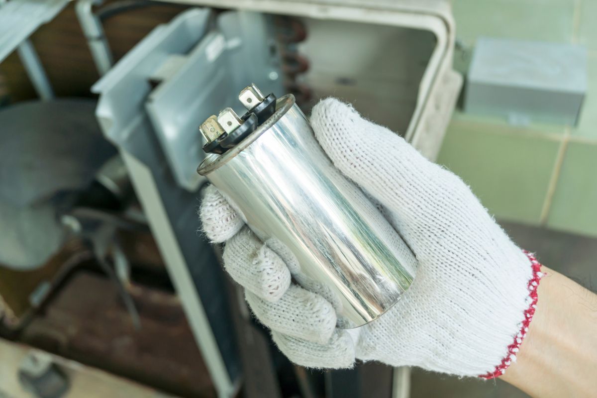
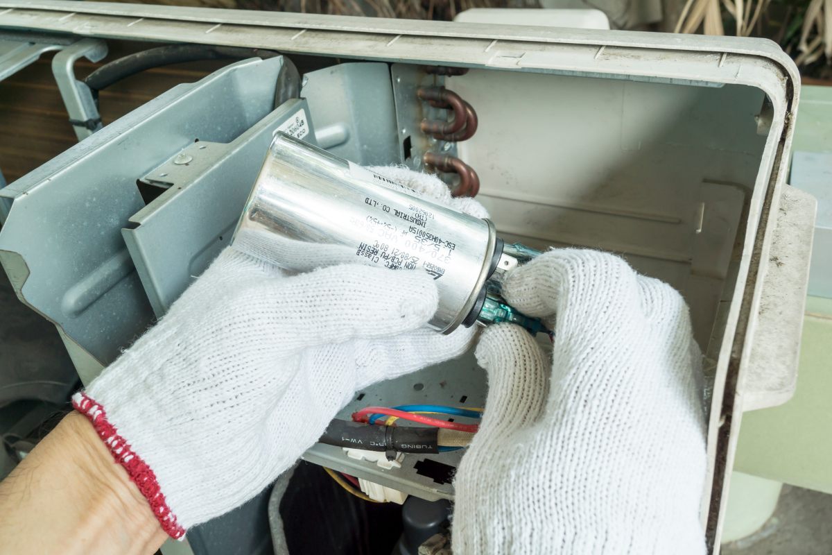
AC capacitors are typically cylindrical and come in various sizes depending on their capacitance and voltage rating. They’re usually housed in a metal casing (often aluminum) and contain a dielectric material, frequently metallized polypropylene film. The capacitor’s markings clearly show its capacitance (in µF, or microfarads), voltage rating (in VAC, or volts AC), and often its tolerance (in %). When replacing a capacitor, it’s crucial to use one with the correct capacitance and voltage rating. Using a capacitor with too little capacitance will starve the motor of power, hindering starting or running. On the flip side, using a capacitor with too much capacitance can damage the motor windings (the wires inside the motor). And using a capacitor with the wrong voltage rating can lead to capacitor failure and potential safety hazards. Don’t assume physical size is the only factor! Capacitors with the same physical dimensions can have vastly different capacitance and voltage ratings. Always, always match the µF and VAC ratings exactly to the original capacitor or the manufacturer’s specifications. Using an incorrectly rated capacitor can damage your AC unit’s motor or cause the new capacitor to fail prematurely. Safety first!
Common Reasons for AC Capacitor Failure
Just like any other electronic component, capacitors have a limited lifespan. Over time, the insulating material (dielectric) between the capacitor plates naturally degrades, a process known as dielectric breakdown. Think of it like the insulation on an old wire cracking and becoming less effective. This breakdown reduces the capacitor’s ability to store charge effectively. Factors like heat and voltage stress can accelerate this aging process. The lifespan of an AC capacitor can vary quite a bit depending on things like operating temperature, how often you use your AC, and the quality of your power supply. While there’s no hard and fast rule, a well-maintained capacitor in a typical home AC unit might last 5-10 years, or even longer. However, it’s a good idea to inspect and test them regularly to catch potential problems before they lead to complete failure. Some HVAC pros even recommend replacing them every few years, especially if you live in a hot climate.
Overheating is a major enemy of capacitors. Excessive operating temperature is a significant reason why they fail. Where does this heat come from? Well, it could be the ambient temperature around your AC unit, the heat generated by the motor itself, or even poor ventilation around the unit. Heat accelerates the breakdown of the dielectric material inside the capacitor. Think of it like cooking an egg: high temperatures cause the dielectric material to degrade more rapidly, reducing its insulating properties and leading to increased leakage current (a small amount of current that “leaks” through the dielectric) and, eventually, failure. Capacitors located near hot components, like the compressor, are especially prone to overheating.
Power surges, or sudden spikes in voltage, are another threat to capacitors. Think of it like a sudden flood of electricity. These spikes can exceed the capacitor’s voltage rating, which is like exceeding the maximum water level a dam can hold, causing the dielectric to break down. While some capacitors have built-in protection, it’s a good idea to use external surge protectors to provide extra safety for your entire AC system. Lightning strikes are a common cause of these damaging power surges, so it’s definitely something to consider.
Although less common than age or overheating, manufacturing defects can also lead to premature capacitor failure. These defects might include impurities in the dielectric material, poor connections between the terminals and the plates, or other imperfections in how the capacitor was put together. Higher-quality capacitors typically undergo more rigorous quality control, which reduces the chances of these manufacturing defects. It’s also worth noting that capacitors often come with a limited warranty, which may cover failures caused by manufacturing defects.
Incorrect installation can also spell disaster for capacitors. Examples of improper installation include reversing the polarity on polarized capacitors (if your capacitor has a positive and negative side, it’s crucial to connect them correctly) or using the wrong type of capacitor (like using a run capacitor where a start capacitor is needed, or vice versa). Always follow the manufacturer’s instructions carefully when installing a capacitor. They’re there for a reason!
Maybe You Are Interested In
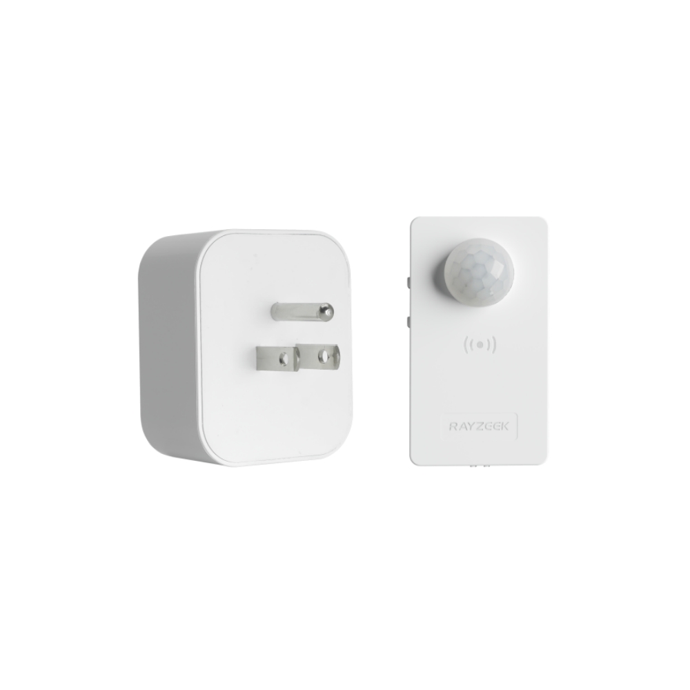
- Voltage: 2 x AAA Batteries OR 5V DC
- Transmission Distance: up to 30m
- Day/Night mode
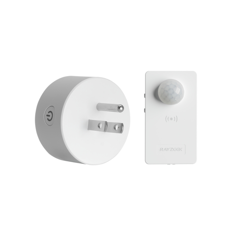
- Voltage: 2 x AAA Batteries OR 5V DC
- Transmission Distance: up to 30m
- Day/Night mode
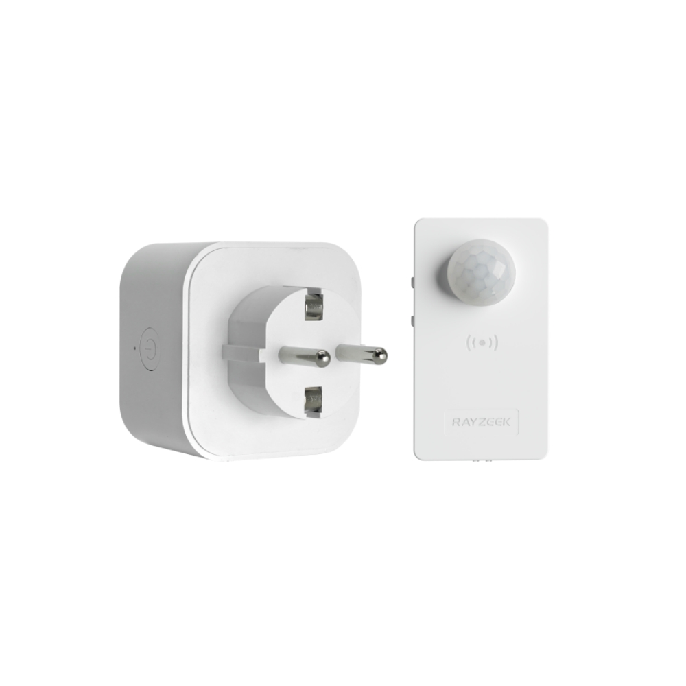
- Voltage: 2 x AAA
- Transmission Distance: 30 m
- Time delay: 5s, 1m, 5m, 10m, 30m
- Load Current: 10A Max
- Auto/Sleep Mode
- Time delay: 90s, 5min, 10min, 30min, 60min
- Load Current: 10A Max
- Auto/Sleep Mode
- Time delay: 90s, 5min, 10min, 30min, 60min
- Load Current: 10A Max
- Auto/Sleep Mode
- Time delay: 90s, 5min, 10min, 30min, 60min
- Load Current: 10A Max
- Auto/Sleep Mode
- Time delay: 90s, 5min, 10min, 30min, 60min
- Load Current: 10A Max
- Auto/Sleep Mode
- Time delay: 90s, 5min, 10min, 30min, 60min
- Load Current: 10A Max
- Auto/Sleep Mode
- Time delay: 90s, 5min, 10min, 30min, 60min
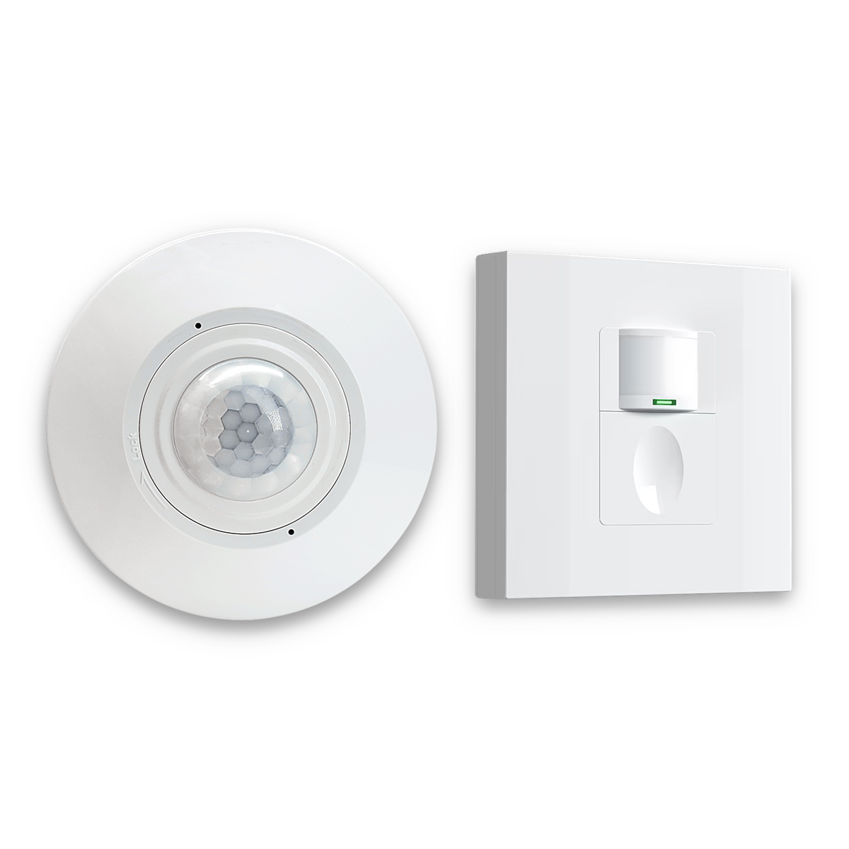
- Occupancy mode
- 100V ~ 265V, 5A
- Neutral Wire Required
- 1600 sq ft
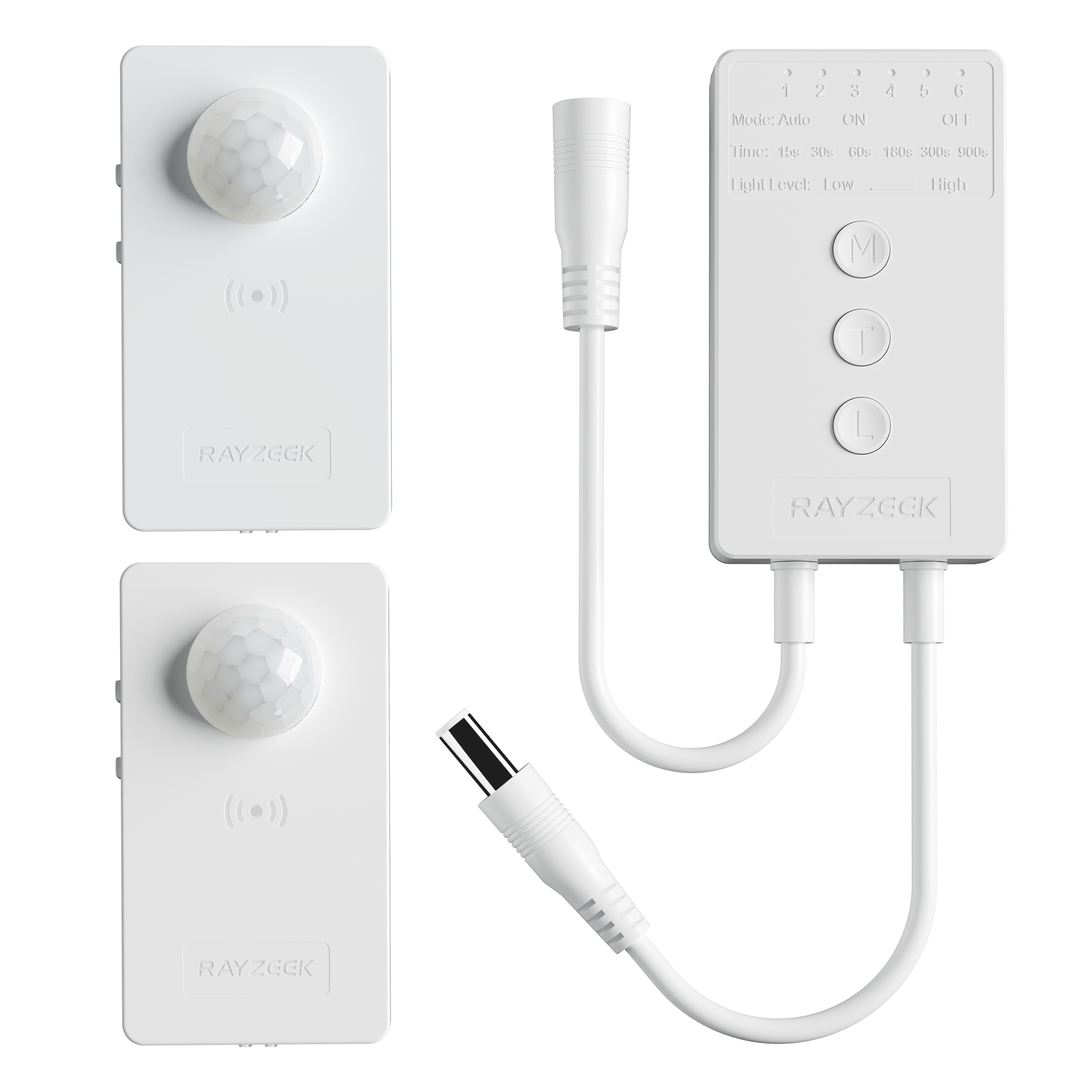
- Voltage: DC 12v/24v
- Mode: Auto/ON/OFF
- Time Delay: 15s~900s
- Dimming: 20%~100%
- Occupancy, Vacancy, ON/OFF mode
- 100~265V, 5A
- Neutral Wire Required
- Fits the UK Square backbox
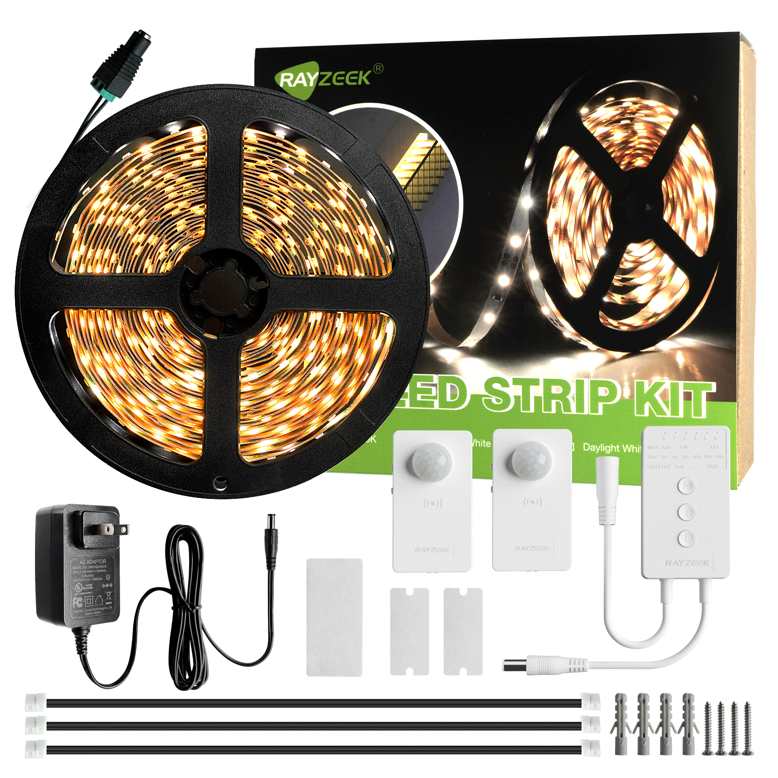
- Voltage: DC 12V
- Length: 2.5M/6M
- Color Temperature: Warm/Cold White
- Voltage: DC 12V
- Length: 2.5M/6M
- Color Temperature: Warm/Cool White
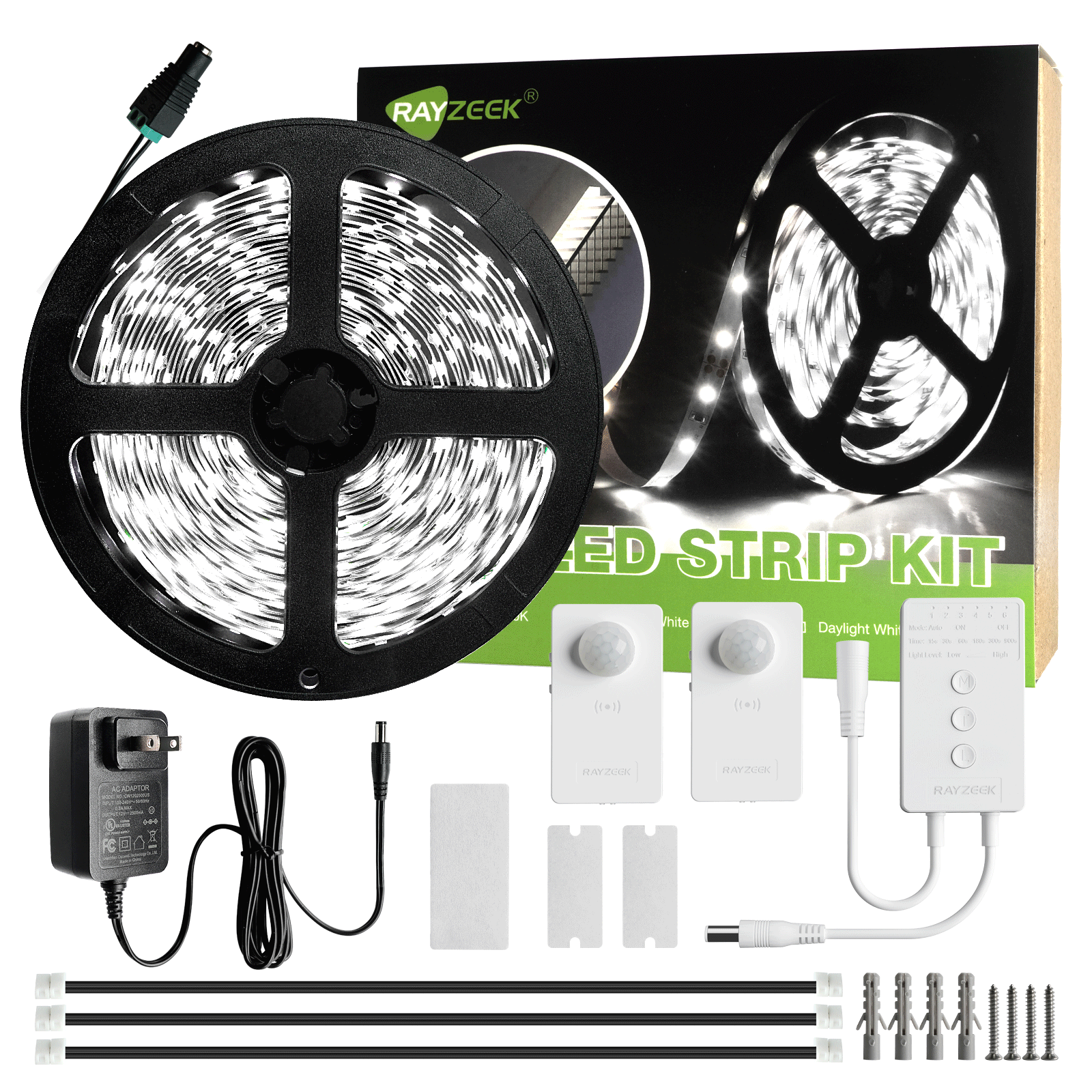
- Voltage: DC 12V
- Length: 2.5M/6M
- Color Temperature: Warm/Cool White
- Voltage: DC 12V
- Length: 2.5M/6M
- Color Temperature: Warm/Cold White
- Occupancy mode
- 12V ~ 24V, 5A
- Neutral Wire Required
- 1600 sq ft
- Voltage: DC 12v/24v
- Day/Night Mode
- Time delay: 15min, 30min, 1h(default), 2h
- Occupancy, Vacancy, ON/OFF mode
- 120V 5A
- Neutral Wire Required
- Fits the US 1-Gang wall box
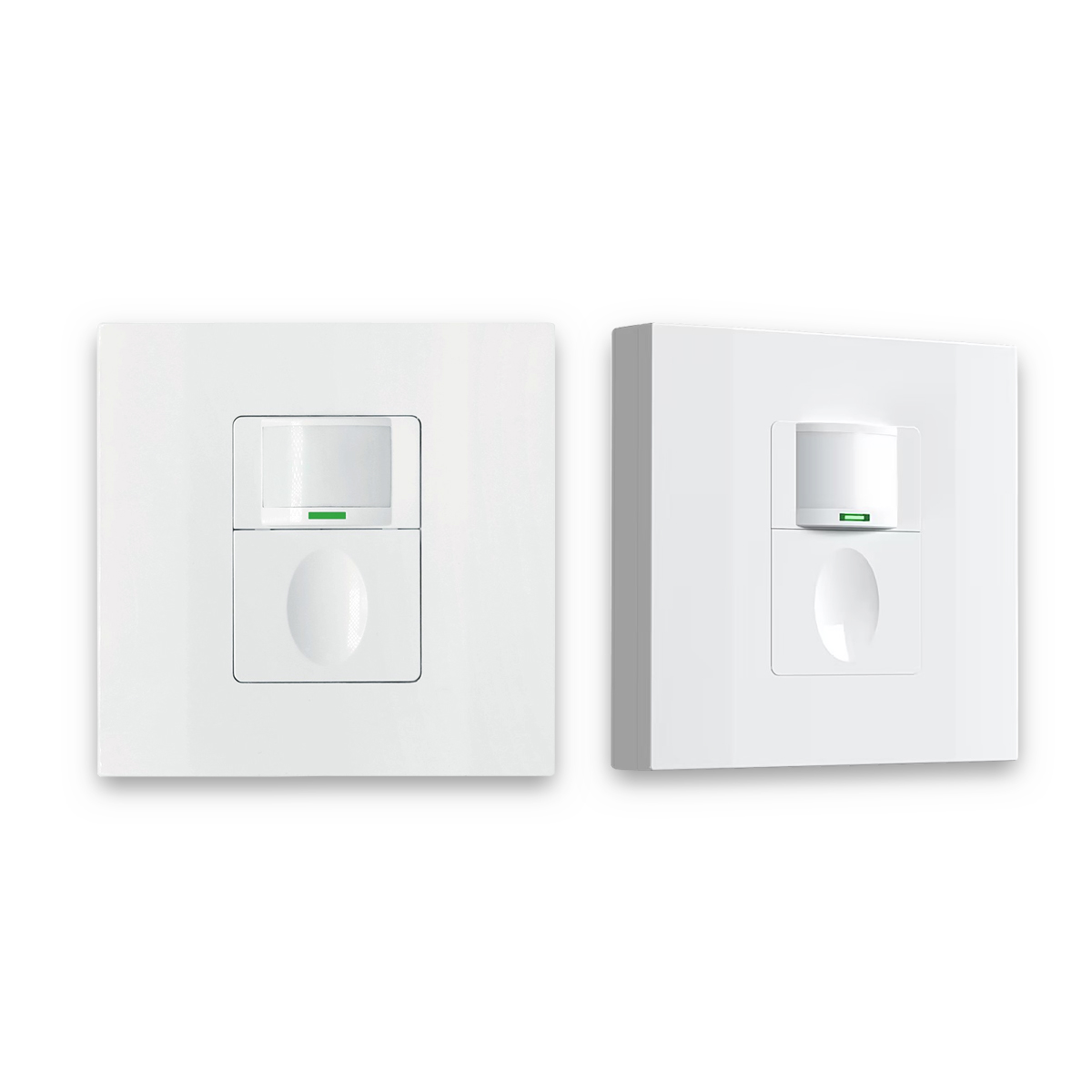
- Occupancy, Vacancy, ON/OFF mode
- 120V, 5A
- Neutral Wire Required
- Fits the US 1-Gang wall box
Visual Signs of a Bad AC Capacitor
One of the most obvious visual signs of a failing capacitor is bulging. If the top or sides of the capacitor are swollen or misshapen, that’s a red flag. This bulging is caused by internal pressure buildup due to the breakdown of the dielectric material and the formation of gases inside. A bulging capacitor is a clear sign of failure and should be replaced immediately.
Leaking fluid is another sign to watch out for. If you see an oily residue around the capacitor, it’s likely leaking. This fluid is usually a dielectric oil used in some types of capacitors. The presence of leaking fluid indicates that the capacitor’s seal has been compromised, and it’s losing its dielectric material.
A burnt smell or visible signs of burning are a major cause for concern. If you notice discoloration or charring on the capacitor or surrounding components, it indicates a serious problem. This is usually caused by overheating or electrical arcing (when electricity jumps across a gap) within the capacitor. A burnt capacitor represents a potential fire hazard and should be addressed immediately.
Corrosion, like rust or other forms of decay on the capacitor’s terminals (the connection points) or casing, can also indicate a potential problem. Corrosion is often caused by exposure to moisture or corrosive environments. It can lead to poor electrical connections, which can hinder the capacitor’s performance.
Any visible physical damage, such as cracks, dents, or other deformities in the capacitor’s casing, should be a cause for concern. This damage can be caused by mechanical impact or stress. Physical damage can compromise the capacitor’s integrity and its ability to function correctly.
It’s important to remember that a capacitor can fail without showing any of these visual signs. So, while a visual inspection is a good first step, it’s only a preliminary one. To really know if a capacitor is functioning correctly, you’ll need to perform electrical testing with a multimeter (a handy tool for measuring electrical values).
Get Inspired by Rayzeek Motion Sensor Portfolios.
Doesn't find what you want? Don't worry. There are always alternate ways to solve your problems. Maybe one of our portfolios can help.
How to Safely Discharge an AC Capacitor
Before you even think about handling an AC capacitor, it’s absolutely essential to discharge it for your safety. Capacitors store electrical energy, even when the power to the AC unit is turned off. Touching the terminals of a charged capacitor can result in a painful and potentially dangerous electrical shock. The severity of the shock depends on the capacitor’s voltage (electrical pressure) and capacitance (how much energy it can store), but it can range from a mild jolt to a serious injury. It can also damage sensitive electronic components if you are grounded.
To safely discharge an AC capacitor, you’ll need a few specific tools:
- An insulated screwdriver or, preferably, a resistor (20,000 ohms, 2-5 watts) with insulated leads.
- Why this specific resistor value? It provides a safe discharge rate – not too fast (which could damage the capacitor) and not too slow (which would be impractical).
- Wattage rating importance: It ensures the resistor can handle the energy dissipated during discharge without overheating.
Follow these steps to safely discharge the capacitor:
- Disconnect power: Disconnect power to the AC unit at the breaker box. (Remember, safety first!)
- Locate the capacitor: Find the capacitor within the AC unit (usually near the compressor or fan motor).
- Discharge using a resistor (preferred method): Connect the resistor leads across the capacitor terminals (the metal connection points) for several seconds (at least 5-10 seconds).
- How to connect: Hold the insulated leads, not the resistor body or bare wires. (Use insulated tools!)
- Discharge using an insulated screwdriver (alternative method, use with extreme caution): Briefly touch the metal shaft of the screwdriver across the capacitor terminals. This method is less preferred because it creates a rapid discharge, potentially causing a large spark and potentially damaging the capacitor, the screwdriver, or even causing injury. Always prioritize using a resistor.
- Verify discharge with a voltmeter: Set the voltmeter to DC voltage (a setting on your meter) and measure the voltage across the terminals. It should read zero volts.
- Why this is crucial: It ensures the capacitor is completely discharged before you handle it.
Always follow these safety precautions:
- Wear insulated gloves and eye protection.
- Use insulated tools.
- Double-check that the power is off.
- Never touch the capacitor terminals (the metal connection points) directly with your bare hands.
Important Safety Precautions
When working with AC capacitors, always follow these safety precautions:
- Disconnect Power: Always disconnect the power to the AC unit at the breaker box before accessing or working on any electrical components, including the capacitor.
- Why this is crucial: It prevents electrical shock.
- Double-check: Use a non-contact voltage tester (a tool that detects voltage without touching wires) to verify that the power is off.
- Discharge the Capacitor: Always discharge the capacitor before handling, as detailed in the previous section.
- Use Insulated Tools: Use tools with insulated handles to prevent electrical shock.
- Wear Safety Gear: Wear safety glasses or a face shield to protect your eyes from sparks or debris. Wear insulated gloves to protect your hands.
- Work in a Well-Ventilated Area: Some capacitors may contain small amounts of hazardous materials.
- Be Aware of Surroundings: Ensure the work area is clear of obstructions and potential hazards.
- Consult a Professional: If you are uncomfortable or unsure about any part of the process, consult a qualified HVAC technician.
- When to call a professional: If you are not experienced with electrical work, if the capacitor is difficult to access, or if you suspect other problems with the AC unit.
- High Voltage Warning: AC capacitors operate at high voltages, even when the unit is off, making safety paramount.
How to Test with a Multimeter
A multimeter is your best bet for accurately testing a capacitor’s capacitance (its ability to store charge) and figuring out if it’s in good shape.
There are two main types of multimeters: analog and digital. Analog multimeters are the older style and less common for testing capacitance. Digital multimeters (DMMs) are generally preferred because they’re more accurate and easier to use. Within digital multimeters, you’ll find auto-ranging and manual-ranging models. Auto-ranging multimeters automatically select the appropriate measurement range, while manual-ranging multimeters require you to select the range yourself. If you have a manual-ranging multimeter, you’ll need to choose a range that’s higher than the expected capacitance of the capacitor you’re testing.
To test a capacitor, your multimeter needs a couple of key features: First, it must have a capacitance measurement mode – a setting specifically designed for measuring capacitance (usually indicated by a capacitor symbol or “µF” on the dial). Second, it needs a sufficient range – the multimeter’s capacitance range must be higher than the expected capacitance of the capacitor you’re testing.
Setting Your Multimeter
The first step is to set your multimeter to measure capacitance. Turn the multimeter’s dial to the capacitance measurement setting. Look for the common capacitor symbol (often a sideways “U” with a vertical line) or the letters “CAP” or “µF”.
If your multimeter is auto-ranging, you’re in luck! It will automatically select the appropriate range for the measurement.
If your multimeter is manual-ranging, you’ll need to select a range that is higher than the expected capacitance of the capacitor you’re testing. For example, if you’re testing a 35µF capacitor, select the 200µF range (if available) or the next highest range. If the range is too low, the multimeter may display an “OL” (overload) reading. If the range is too high, the reading may be less precise. For example, if you use the 2000µF range to measure a 35µF capacitor, the multimeter might only display ’35’, whereas the 200µF range might display ‘35.2’.
Some multimeters have a “REL” (relative) or zeroing function for capacitance measurements. This function compensates for the internal capacitance of the meter and leads, giving you a more accurate reading. To use this function, consult your multimeter’s manual for specific instructions.
Connecting the Probes
Before connecting the multimeter probes (the wires that come with your multimeter), make sure the capacitor is completely disconnected from the AC unit’s wiring. This prevents inaccurate readings and potential damage to your multimeter.
Now, let’s talk about polarity. Most AC run capacitors are non-polarized, which means it doesn’t matter which probe you connect to which terminal (the connection points on the capacitor).
However, some start capacitors are polarized, and it’s crucial to connect the probes correctly. Polarized capacitors are usually clearly marked with a “+” and “-” sign near the terminals (the connection points).
Reversing the polarity on a polarized capacitor can damage the capacitor and potentially your multimeter. For non-polarized capacitors, you can connect the probes to either terminal. For polarized capacitors, connect the positive (red) probe to the positive (+) terminal and the negative (black) probe to the negative (-) terminal.
Make sure the probes make good, solid contact with the capacitor terminals. If the terminals are corroded, clean them with a wire brush or fine-grit sandpaper before testing to ensure a good connection.
Looking For Motion-Activated Energy-Saving Solutions?
Contact us for complete PIR motion sensors, motion-activated energy-saving products, motion sensor switches, and Occupancy/Vacancy commercial solutions.
Interpreting the Readings
When you connect the probes, the multimeter should display a reading in microfarads (µF). This reading should be close to the capacitor’s rated capacitance, which is printed right on the capacitor itself.
Capacitors have a tolerance range, which indicates the acceptable variation from the rated capacitance. Common tolerance ranges are ±5% or ±10%. For example, a 35µF capacitor with a ±5% tolerance could have a reading between 33.25µF (35 – 1.75) and 36.75µF (35 + 1.75) and still be considered within the acceptable range.
A reading significantly below the rated capacitance (typically more than 10% below, and often even less, like 5%) indicates a weak or failing capacitor. For example, a 35µF capacitor reading 30µF or lower is likely on its way out. The consequences of a weak capacitor? Reduced motor performance, overheating, and potential motor failure.
A reading of zero, “OL” (overload), or an extremely low value indicates an open capacitor, which means there’s an internal break in the circuit. The consequence? The motor won’t start or run.
A very low resistance reading (close to zero ohms) when the multimeter is set to resistance mode after discharging indicates a shorted capacitor. This is a relatively rare but very dangerous condition. A shorted capacitor can cause extremely high current flow when power is applied, potentially damaging other components in the AC unit and posing a fire hazard. The consequence? Excessive current flow and damage to other components.
It’s a good idea to take several readings to make sure they’re consistent and to rule out any intermittent issues.
Keep in mind that the capacitance of a capacitor can be slightly affected by temperature. For the most accurate readings, test the capacitor at room temperature.
Always compare the reading to the value printed on the capacitor itself, not to a value you might find elsewhere (like on a schematic diagram). Compare the reading to the capacitor’s rated capacitance, voltage, and tolerance, as indicated by the markings on the capacitor itself.
Understanding Capacitor Failure Causes
Let’s dive a bit deeper into the mechanisms that cause capacitors to fail.
- Dielectric Breakdown: Over time and under stress, the dielectric material develops microscopic conductive pathways. Think of it like tiny cracks forming in the insulation, allowing current to “leak” between the capacitor plates and reducing its ability to hold a charge effectively.
- Electrochemical reactions: In electrolytic capacitors, chemical reactions can contribute to degradation. The electrolyte (a conductive liquid or gel) can react with the dielectric or the electrodes (the metal plates), leading to changes in their properties and ultimately, failure.
- Self-healing (metallized film capacitors): Some capacitors, like metallized film capacitors, have a neat “self-healing” property. They have a thin layer of metal deposited on the dielectric film. If a small breakdown occurs, the high current at the fault location can vaporize the metal around the breakdown, effectively isolating the fault and preventing a complete short circuit. However, this self-healing process consumes a small amount of the metallization, and repeated breakdowns will eventually lead to a significant reduction in capacitance.
- Electrode Degradation: Corrosion, often caused by moisture or chemical exposure, can increase the resistance of the electrodes and connections, leading to reduced performance and eventual failure.
- Electromigration: (Less common in AC capacitors) This is the movement of metal ions under high current density, which can lead to open circuits or shorts.
- Mechanical Stress: Prolonged vibration can loosen internal connections or cause fatigue in the capacitor’s materials, leading to failure. Repeated heating and cooling (thermal expansion and contraction) can also cause stress on the capacitor’s components. The different materials within the capacitor expand and contract at different rates, creating stress that can lead to cracks or delamination over time.
Several external factors can also contribute to capacitor failure:
- Power Quality Issues:
- Harmonic distortion: Harmonics are like unwanted “noise” in your power supply. They are multiples of the fundamental power frequency (e.g., 120Hz, 180Hz for a 60Hz system). This harmonic distortion can cause increased heating and stress on the capacitor, leading to premature failure.
- Voltage fluctuations: Frequent voltage variations, like voltage sags (dips) or swells (surges), can stress the dielectric material, accelerating its breakdown.
- Operating Environment:
- Temperature extremes: Very high or very low temperatures can affect capacitor performance and lifespan. Extreme temperatures can affect the dielectric properties and accelerate degradation.
- Humidity: High humidity can lead to corrosion and dielectric breakdown. It can accelerate corrosion and also directly affect the dielectric material, reducing its insulating properties.
- Dust and contaminants: Dust and other contaminants can affect cooling and potentially cause short circuits. Dust buildup can restrict airflow and lead to overheating. Conductive contaminants can create short circuits between the terminals or within the capacitor.
For HVAC professionals, figuring out the root cause of capacitor failure can be valuable for preventing future failures. This might involve analyzing the operating conditions (how the AC unit is used), power quality (the stability of the electrical supply), and the capacitor’s design. For example, if capacitors are consistently failing prematurely, it might indicate a problem with the AC unit’s design, the power supply, or the operating environment. While all capacitors are susceptible to failure, the quality of materials and manufacturing processes can significantly impact their lifespan and reliability. Lower-cost capacitors may use thinner dielectric materials, less robust connections, and have poorer quality control, leading to a higher risk of premature failure. Higher-quality capacitors, often from reputable manufacturers, tend to use more durable materials, have better construction, and undergo more rigorous testing, resulting in a longer lifespan and improved performance. Common failure modes in lower-quality capacitors include more rapid dielectric breakdown and increased susceptibility to voltage surges. Choosing a capacitor with a higher temperature rating and a longer warranty period can often be an indicator of better quality.
A failing capacitor, especially a run capacitor, can significantly reduce the overall efficiency of your AC unit. When a capacitor’s capacitance drops below its rated value, the motor operates less efficiently, drawing more current to produce the same amount of cooling power. This increased current leads to higher energy consumption and increased wear and tear on the motor. A weak capacitor can also cause the motor to overheat, further reducing efficiency and potentially leading to premature motor failure. The reduced power factor caused by a failing run capacitor also contributes to energy waste.
Testing an AC capacitor is a crucial step in diagnosing and maintaining air conditioning systems. By understanding the function of the capacitor, recognizing the signs of failure, and utilizing proper testing procedures with a multimeter, both homeowners and HVAC professionals can identify and address capacitor problems effectively. Regular inspection and testing, combined with an understanding of the factors that contribute to capacitor failure, can help ensure the efficient and reliable operation of your AC unit. And looking ahead, advancements in sensor technology are enabling predictive maintenance for AC systems. Smart sensors can monitor various parameters, including capacitor health, in real-time, potentially identifying impending failures before they lead to system breakdowns. This allows for proactive maintenance and can help extend the lifespan of AC units. So, stay informed, stay safe, and keep your AC running smoothly!